IPv4 and IPv6 dual-stack PPPoE
March 13, 2014 8 Comments
The lab covers a scenario of adding basic IPv6 access to an existing PPPoE (PPP for IPv4).
PPPoE is established between CPE (Client Premise Equipment) the PPPoE client and the PPPoE server also known as BNG (Broadband Network Gateway).

Figure1: ipv4 and IPv6 dual-stack PPPoe
PPPoE server plays the role of the authenticator (local AAA) as well as the authentication and address pool server (figure1). Obviously, a higher centralized prefix assignment and authentication architecture (using AAA RADIUS) is more scalable for broadband access scenarios (figure2).
For more information about RADIUS attributes for IPv6 access networks, start from rfc6911 (http://www.rfc-editor.org/rfc/rfc6911.txt).
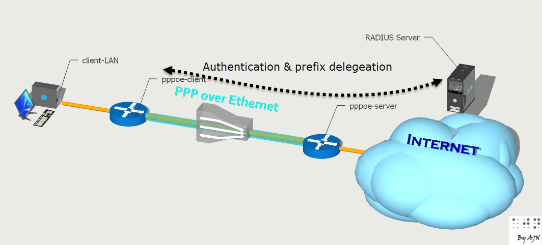
Figure2: PPPoE with RADIUS
PPPoE for IPv6 is based on the same PPP model as for PPPoE over IPv4. The main difference in deployment is related to the nature of the routed protocol assignment to CPEs (PPPoE clients).
- IPv4 in routed mode, each CPE gets its WAN interface IP centrally from the PPPoE server and it’s up to the customer to deploy an rfc1918 prefix to the local LAN through DHCP.
- PPPoE client gets its WAN interface IPv6 address through SLAAC and a delegated prefix to be used for the LAN segment though DHCPv6.
Animation: PPP encapsulation model
Let’s begin with a quick reminder of a basic configuration of PPPoE for IPv4.
PPPoE for IPv4
pppoe-client WAN address assignment
The main steps of a basic PPPoE configuration are:
- Create a BBAG (BroadBand Access Group).
- Tie the BBAG to virtual template interface
- Assign a loopback interface IP (always UP/UP) to the virtual template.
- Create and assign the address pool (from which client will get their IPs) to the virtual template interface.
- Create local user credentials.
- Set the authentication type (chap)
- Bind the virtual template interface to a physical interface (incoming interface for dial-in).
- The virtual template interface will be used as a model to generate instances (virtual access interfaces) for each dial-in session.

Figure3: PPPoE server model
pppoe-server
| ip local pool PPPOE_POOL 172.31.156.1 172.31.156.100 ! bba-group pppoe BBAG virtual-template 1 ! interface Virtual-Template1 ip unnumbered Loopback0 ip mtu 1492 peer default ip address pool PPPOE_POOL ppp authentication chap callin ! interface FastEthernet0/0 pppoe enable group BBAG |
pppoe-client
| interface FastEthernet0/1 pppoe enable group global pppoe-client dial-pool-number 1 ! interface FastEthernet1/0 ip address 192.168.0.201 255.255.255.0 ! interface Dialer1 mtu 1492 ip address negotiated encapsulation ppp dialer pool 1 dialer-group 1 ppp authentication chap callin ppp chap hostname pppoe-client ppp chap password 0 cisco |

Figure4: PPPoE client model
As mentioned in the beginning, DHCPv4 is deployed at the CPE device to assign rfc1819 addresses to LAN clients and then translated, generally using PAT (Port Address Translation) with the assigned IPv4 to the WAN interface.
You should have the possibility to configure static NAT or static port-mapping to give public access to internal services.
Address translation
| interface Dialer1 ip address negotiated ip nat outside ! interface FastEthernet0/0 ip address 192.168.4.1 255.255.255.224 ip nat inside ! ip nat inside source list NAT_ACL interface Dialer1 overload ! ip access-list standard NAT_ACL permit any |
pppoe-client LAN IPv4 address assignment
pppoe-client
| ip dhcp excluded-address 192.168.4.1 ! ip dhcp pool LAN_POOL network 192.168.4.0 255.255.255.224 domain-name cciethebeginning.wordpress.com default-router 192.168.4.1 ! interface FastEthernet0/0 ip address 192.168.4.1 255.255.255.224 |
PPPoE for IPv6
pppoe-client WAN address assignment
All IPv6 prefixes are planned from the 2001:db8::
Pppoe-server
| ipv6 local pool PPPOE_POOL6 2001:DB8:5AB:10::/60 64 ! bba-group pppoe BBAG virtual-template 1 ! interface Virtual-Template1 ipv6 address FE80::22 link-local ipv6 enable ipv6 nd ra lifetime 21600 ipv6 nd ra interval 4 3
ppp authentication chap callin ! interface FastEthernet0/0 pppoe enable group BBAG |
IPCP (IPv4) negotiates the IPv4 address to be assigned to the client, where IPC6CP negotiates only the interface identifier, the prefix information is performed through SLAAC.
pppoe-client
| interface FastEthernet0/1 pppoe enable group global pppoe-client dial-pool-number 1 ! interface Dialer1 mtu 1492 dialer pool 1 dialer-group 1 ipv6 address FE80::10 link-local ipv6 address autoconfig default ipv6 enable ppp authentication chap callin ppp chap hostname pppoe-client ppp chap password 0 cisco |
The CPE (PPPoE client) is assigned an IPv6 address through SLAAC along with a static default route: ipv6 address autoconfig default
| pppoe-client#sh ipv6 interface dialer 1 Dialer1 is up, line protocol is up IPv6 is enabled, link-local address is FE80::10 No Virtual link-local address(es): Stateless address autoconfig enabled Global unicast address(es): 2001:DB8:5AB:10::10, subnet is 2001:DB8:5AB:10::/64 [EUI/CAL/PRE] valid lifetime 2587443 preferred lifetime 600243 |
Note from the below traffic capture (figure5) that both IPv6 and IPv4 use the same PPP session (layer2 model) (same session ID=0x0006) because the Link Control Protocol is independent of the network layer.

Figure5: Wireshark capture of common PPP layer2 model
pppoe-client LAN IPv6 assignment
The advantage of using DHCPv6 PD (Prefix Delegation is that the PPPoE will automatically add a static route to the assigned prefix, very handy!
pppoe-server
| ipv6 dhcp pool CPE_LAN_DP prefix-delegation 2001:DB8:5AB:2000::/56 00030001CA00075C0008 lifetime infinite infinite ! interface Virtual-Template1 ipv6 dhcp server CPE_LAN_DP |
Now the PPPoE client can use the delegated prefix to assign an IPv6 address (::1) to its own interface (fa0/0) and the remaining for SLAAC advertisement.
No NAT needed for the delegated prefixes to be used publically, so no translation states on the PPPoE server. The prefix is directly accessible from outside.
For more information about the client ID used for DHCPv6 assignment, please refer to the prior post about DHCPv6. https://cciethebeginning.wordpress.com/2012/01/18/ios-dhcpv6-deployment-schemes/
pppoe-client
| pppoe-client#sh ipv6 dhcp This device’s DHCPv6 unique identifier(DUID): 00030001CA00075C0008 pppoe-client# |
| interface Dialer1 ipv6 dhcp client pd PREFIX_FROM_ISP ! interface FastEthernet0/0 ipv6 address FE80::2000:1 link-local ipv6 address PREFIX_FROM_ISP ::1/64 ipv6 enable |
| pppoe-client#sh ipv6 dhcp interface Dialer1 is in client mode Prefix State is OPEN Renew will be sent in 3d11h Address State is IDLE List of known servers: Reachable via address: FE80::22 DUID: 00030001CA011F780008 Preference: 0 Configuration parameters: IA PD: IA ID 0x00090001, T1 302400, T2 483840 Prefix: 2001:DB8:5AB:2000::/56 preferred lifetime INFINITY, valid lifetime INFINITY Information refresh time: 0 Prefix name: PREFIX_FROM_ISP Prefix Rapid-Commit: disabled Address Rapid-Commit: disabled |
client-LAN
Now the customer LAN is assigned globally available IPv6 from the CPE (PPPoE client).
| client-LAN#sh ipv6 interface fa0/0 FastEthernet0/0 is up, line protocol is up IPv6 is enabled, link-local address is FE80::2000:F No Virtual link-local address(es): Stateless address autoconfig enabled Global unicast address(es): 2001:DB8:5AB:2000::2000:F, subnet is 2001:DB8:5AB:2000::/64 [EUI/CAL/PRE] |
| client-LAN#sh ipv6 route … S ::/0 [2/0] via FE80::2000:1, FastEthernet0/0 C 2001:DB8:5AB:2000::/64 [0/0] via FastEthernet0/0, directly connected L 2001:DB8:5AB:2000::2000:F/128 [0/0] via FastEthernet0/0, receive L FF00::/8 [0/0] via Null0, receive client-LAN# |
End-to-end dual-stack connectivity check
| client-LAN#ping 2001:DB8:5AB:3::100 Type escape sequence to abort. Sending 5, 100-byte ICMP Echos to 2001:DB8:5AB:3::100, timeout is 2 seconds: !!!!! Success rate is 100 percent (5/5), round-trip min/avg/max = 20/45/88 ms client-LAN#trace 2001:DB8:5AB:3::100 Type escape sequence to abort. Tracing the route to 2001:DB8:5AB:3::100 1 2001:DB8:5AB:2000::1 28 msec 20 msec 12 msec 2 2001:DB8:5AB:2::FF 44 msec 20 msec 32 msec 3 2001:DB8:5AB:3::100 48 msec 20 msec 24 msec client-LAN# |
| client-LAN#ping 192.168.3.100 Type escape sequence to abort. Sending 5, 100-byte ICMP Echos to 192.168.3.100, timeout is 2 seconds: !!!!! Success rate is 100 percent (5/5), round-trip min/avg/max = 52/63/96 ms client-LAN#trace 192.168.3.100 Type escape sequence to abort. Tracing the route to 192.168.3.100 1 192.168.4.1 32 msec 44 msec 20 msec 2 192.168.2.1 56 msec 68 msec 80 msec 3 192.168.3.100 72 msec 56 msec 116 msec client-LAN# |
I assigned PREFIX_FROM_ISP as locally significant name for the delegated prefix, no need to match the name on the DHCPv6 server side.
Finally, the offline lab with all the commands needed for more detailed inspection:
References
http://www.broadband-forum.org/technical/download/TR-187.pdf
https://tools.ietf.org/html/rfc5072
https://tools.ietf.org/html/rfc5072
http://www.bortzmeyer.org/6911.html (french)
http://packetsize.net/cisco-pppoe-ipv4-ipv6-mppe.htm


