IPv6 over AToM pseudowire
January 23, 2013 Leave a comment
The purpose of this lab is to show the flexibility of Layer2 VPN technology AToM (Any Transport over MPLS), which allows service providers to smoothly transit the core network from legacy layer2 technologies into a single MPLS infrastructure ready for customer IPv6 transport.
Customer transition from IPv4 to dual stack is as easy as adding an IPv6 configuration to a point-to-point segment.
The lab is organized as follow:
- Lab topology overview
- MPLS Core
- Pseudowire circuit establishment over MPLS
- Customer configuration
- MTU
- Offline Lab
- Quiz
- Conclusion
Lab topology overview
Let’s consider the following lab topology: one core MPLS and three customers. Customer1 uses Ethernet port-to-port layer2 circuit to connect to Provider Edge access router, Customer2 uses Ethernet VLAN layer2 circuit and customer3 uses Frame Relay layer2 circuit.
Picture1: High-level Lab topology

Picture2: Low-level Lab topology

MPLS Core
The MPLS core is configured independently from any pseudowire configuration.
Picture3: MPLS core

In the core MPLS, there is practically nothing special to do. IGP and LDP configuration is straightforward. The goal is to guarantee core stability.
Make sure LDP router id is forced to a loopback interface.
Look here for the router’s main configuration:
http://hpnouri.free.fr/atom/atom-core.swf
Pseudowire circuit establishment over MPLS
Picture4: AToM Pseudowire establishment

The configuration to establish the different pseudowires do not depend on client configuration.
Note for each virtual circuit a directed LDP session is established between PEs connecting customer sites. Each PE uses a /32 loopback IP.
| Layer2 Circuit | PE2 | PE1 |
| Port-to-port | interface FastEthernet0/0 no cdp enable xconnect 22.2.2.2 24 encapsulation mpls |
interface FastEthernet0/0 no cdp enable xconnect 44.4.4.4 24 encapsulation mpls |
| Layer2 Circuit | PE2 | PE1 |
| Vlan | interface FastEthernet1/0 no cdp enable ! interface FastEthernet1/0.10 encapsulation dot1Q 10 xconnect 22.2.2.2 242 encapsulation mpls |
interface FastEthernet1/0 no cdp enable ! interface FastEthernet1/0.10 encapsulation dot1Q 10 xconnect 44.4.4.4 242 encapsulation mpls |
| Layer2 Circuit | PE2 | PE1 |
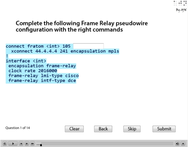
| FR | connect fratom Serial2/0 501 l2transport xconnect 22.2.2.2 241 encapsulation mpls ! interface Serial2/0 encapsulation frame-relay frame-relay lmi-type cisco frame-relay intf-type dce |
connect fratom Serial2/0 105 l2transport xconnect 44.4.4.4 241 encapsulation mpls ! interface Serial2/0 encapsulation frame-relay frame-relay lmi-type cisco frame-relay intf-type dce |
Now, let’s take the east side as example of configuration between clients and the provider edge
Customer configuration
Picture5: Customer circuits
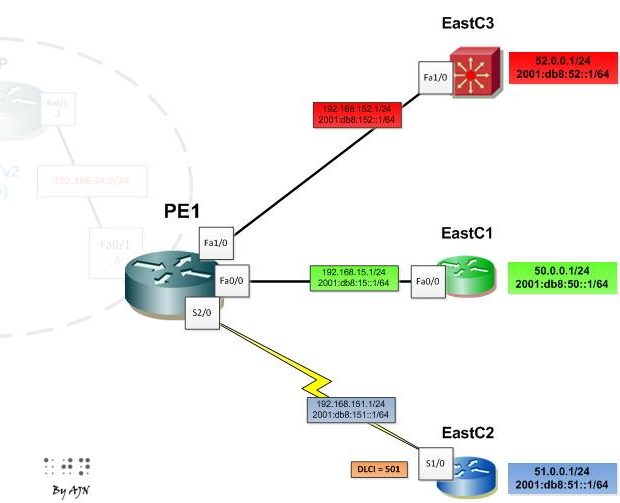
Note the provider edge is configured independently of the client layer3 protocol IPv4/IPv6.
Customer devices are configured in dual stack.
Ethernet port-to-port pseudowire
| East C1 | PE1 | |
| IPv4 | interface FastEthernet0/0 ip address 192.168.15.1 255.255.255.0 ip ospf 15 area 0 |
interface FastEthernet0/0 no cdp enable xconnect 44.4.4.4 24 encapsulation mpls |
| IPv6 | interface FastEthernet0/0 ipv6 address FE80::15:5 link-local ipv6 address 2001:DB8:15::5/64 ipv6 ospf 15 area 0 |
Ethernet vlan pseudowire
| East C3 | PE1 | ||
| IPv4 | interface Vlan10 ip address 192.168.152.1 255.255.255.0 ip ospf 15 area 0 |
interface FastEthernet1/0 switchport access vlan 10 switchport mode trunk |
interface FastEthernet1/0 no cdp enable ! interface FastEthernet1/0.10 encapsulation dot1Q 10 xconnect 44.4.4.4 242 encapsulation mpls |
| IPv6 | interface Vlan10 ipv6 address FE80::152:1 link-local ipv6 address 2001:DB8:152::1/64 ipv6 ospf 15 area 0 |
||
Use sub-interface on PE and disable CDP on the main interface.
FR pseudowire
| East C2 | PE1 | |
| IPv4 | interface Serial1/0 ip address 192.168.151.1 255.255.255.0 encapsulation frame-relay ip ospf network broadcast frame-relay interface-dlci 105 |
connect fratom Serial2/0 105 l2transport xconnect 44.4.4.4 241 encapsulation mpls ! interface Serial2/0 encapsulation frame-relay clock rate 2016000 frame-relay lmi-type cisco frame-relay intf-type dce |
| IPv6 | interface Serial1/0 encapsulation frame-relay ipv6 address FE80::151:5 link-local ipv6 address 2001:DB8:151::5/64 ipv6 enable ipv6 ospf network broadcast ipv6 ospf 15 area 0 frame-relay map ipv6 FE80::151:1 105 frame-relay map ipv6 2001:DB8:151::1 105 broadcast |
For the west side the client configuration is mirrored.
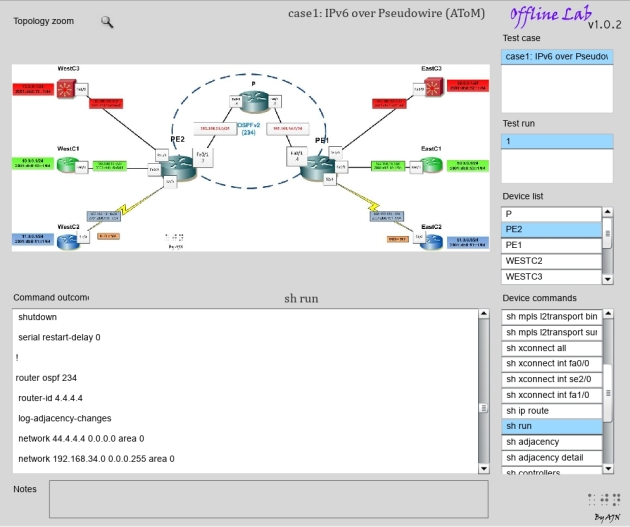
The offline lab provides a complete access to outcomes of large range of commands related to AToM.
The resulting virtual topology looks as follow, typical point-to-point circuits between client devices:
Picture6: Logical connections

MTU
Let’s analyse the path for each type of AToM:
- VC label (identify the pseudowire) = 4 bytes
- LDP Core switching label = 4 bytes
- AToM header for Ethernet = 4 bytes (empty)
- AToM header for Frame Relay = 4 bytes
- Ethernet port-to-port = 14 bytes
- Ethernet VLAN = 14 bytes (Ethernet port-to-port) + 4 bytes (VLAN tag) = 18 bytes
- Frame Relay encapsulation (Cisco) = 2 bytes.
Ethernet port-to-port AToM
| Edge MTU | AToM header for Ethernet | Ethernet port-to-port | LDP Core switching label | VC label | |
| 1500 | 4 (empty) | 14 | 4 | 4 | 1526 bytes |
Ethernet VLAN AToM
| Edge MTU | AToM header for Ethernet | Ethernet VLAN | LDP Core switching label | VC label | |
| 1500 | 4 (empty) | 18 | 4 | 4 | 1530 bytes |
FR AToM
| Edge MTU | AToM header for FR | FR encapsulation | LDP Core switching label | VC label | |
| 1500 | 4 | 2 | 4 | 4 | 1514 bytes |
Let’s set Max calculated MTU as Interface MTU of P/PE routers
On PE1 (Fa0/1), PE2 (FA0/1) and P (Fa0/0, Fa0/1)
| (config-if)# mtu 1530 |
| #sh int fa1/0 | i MTU MTU 1530 bytes, BW 100000 Kbit/sec, DLY 100 usec, # |
MPLS MTU <= Core interfaces MTU
It is very important to distinguish IOS commands for setting MTU:
Hardware MTU
(config-if)# mtu <>: The maximum packet length the interface can support.
IP MTU
(config-if)# ip mtu <>: The maximum size of a non-labelled IP packet without fragmentation.
MPLS MTU
(config-if)# mpls mtu <>: The maximum size of a labelled IP packet without fragmentation (<= Hardware MTU).
Ivan Pepelnjak provides an excellent article about the difference between different MTU commands.
| PE2#sh mpls int fa0/1 detail Interface FastEthernet0/1: IP labeling enabled (ldp): Interface config LSP Tunnel labeling not enabled BGP labeling not enabled MPLS operational MTU = 1500 PE2# |
Testing end-to-end MTU
Note: Lab limitation
| This lab was performed on GNS3 and I had some difficulties building MPLS core using C7200 platform with IOS 12.4(24) as P router. 3700 platform IOS doesn’t allow me to change Hardware MTU. |
So the following test is done considering the maximum MTU through MPLS core of 1500 bytes.
The ping test is performed on a client site using EoMPLS VLAN to test the MTU limit
| WestC3#ping Protocol [ip]: ipv6 Target IPv6 address: 2001:db8:52::1 Repeat count [5]: Datagram size [100]: 1400 Timeout in seconds [2]: Extended commands? [no]: yes Source address or interface: 2001:db8:12::1 UDP protocol? [no]: Verbose? [no]: Precedence [0]: DSCP [0]: Include hop by hop option? [no]: Include destination option? [no]: Sweep range of sizes? [no]: yes Sweep min size [1400]: Sweep max size [18024]: 1530 Sweep interval [1]: 4 Type escape sequence to abort. Sending 165, [1400..1530]-byte ICMP Echos to 2001:DB8:52::1, timeout is 2 seconds: Packet sent with a source address of 2001:DB8:12::1 !!!!!!!!!!!!!!!!C!. (size 1472) . (size 1476) . (size 1480) . (size 1484) . (size 1488) . (size 1492) . (size 1496) . (size 1500) . (size 1504) . (size 1508) . (size 1512) . (size 1516) . (size 1520) . (size 1524) . (size 1528) … <output omitted> Success rate is 53 percent (88/165), round-trip min/avg/max = 28/136/344 ms WestC3# |
Note that ping fails starting from a packet size of 1472.
EoMPLS VLAN pseudowire adds 30 bytes to 1472 bytes which makes the packet bigger than 1500 bytes (lab max MTU limitation).
In fact, beyond the configured MTU on the core MPLS there is an implicit 18 bytes of the underlying Ethernet.
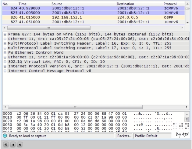
Following an illustrating hopefully clarifies the relationship between different MTUs:

Interactive illustration of Wireshark captured MPLS core transport packet
http://hpnouri.free.fr/atom/wireshark-atom-demo/wireshark-atom-demo.swf
Offline Lab
http://hpnouri.free.fr/atom/offlinelabv1.swf
Quiz
http://hpnouri.free.fr/atom/atom-quiz/atom-quiz.swf
Conclusion
- AToM pseudowires are configured independently of IPv4/IPv6, which makes the client transition from IPv4 to IPv6 transparent.
- From the client point of view it is a directly connected point-to-point circuit.
- Make sure MPLS core interfaces MTU are configured with the maximum packet size and the MPLS MTU is not bigger that interface hardware MTU to avoid unnecessary fragmentation.


